Common Printed Circuit Assembly Errors
Printed circuit assemblies, or PCBs, are used to connect and control electronic components in devices like cell phones, cameras, calculators and drones. These flexible circuits replace wire harnesses to reduce weight, bulk and assembly time. When properly designed and manufactured, flex circuits can move, bend and flex repeatedly without failing or destroying their functionality. However, assembling these circuits on the production line requires a lot of planning and specialized tooling to avoid manufacturing errors.
The first issue faced in a printed circuit assembly is how to support the unique, flexible shape of the circuit. A common solution is to lay the flex circuit down flat on a pallet. This works for single-sided flex circuits, but double-sided flex circuits need to be supported on both sides and at the top and bottom. This requires a custom pallet that can be adjusted to the individual circuit configuration. It’s also important to make sure the pallet is properly fitted, as even a small amount of air underneath the flex circuit can generate mechanical resistance during solder paste screening and SMT pick and place processes.
In addition to pallets, jigs are essential to the assembly of a flex circuit. These jigs are used to hold the flex circuit in place during solder paste screening, SMD mounting and reflow soldering. They are usually custom made for the specific flexible circuit design and include a base, padded board (magnetic or non-magnetic), and steel sheet. They must be designed with the flex circuit’s unique geometry in mind to ensure proper positioning of pin snags and SMD placement. This is done to prevent components from bouncing off the circuit and potentially breaking them, or the circuit itself.
Website design By BotEap.com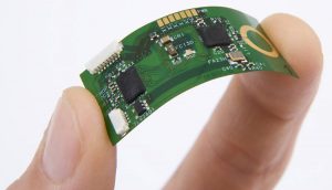
How to Avoid Common Printed Circuit Assembly Errors
Other common flex circuit assembly issues include solder beading – uneven distribution of solder along edges of the flex circuit – and misregistration – components not lined up with their corresponding pads. Solder balls – excess solder that prevents proper fillet formation – and shadowing – where the traces of the flex circuit are obscured by components resulting in shorts – can be avoided with optimized flex PCB assembly process and regular inspection.
To minimize moisture delamination, flex circuits need to be pre-baked prior to assembly. This helps to remove any entrapped moisture that may be present in the dielectric material when the flex circuit and stiffeners reach assembly re-flow temperatures. Moisture that isn’t removed can cause coverlay or layer to layer delaminations and/or stiffener delaminations as it converts to steam at the re-flow temperature.
Proper flex PCB assembly requires the use of specialized test fixtures, including bed of nails and flying probe testers, to get accurate measurements from the electrical nodes on the flex circuit. The bending test checks the flex PCB’s ability to withstand dynamic flexing during usage. The pull strength test tests the solder joints and environmental protection testing confirms that the flex circuit is resistant to damage from vibration, shock, moisture and temperature fluctuations. This is an area where a partnership with an experienced flex circuit assembly manufacturer can greatly improve yield and quality.